If you have a question not addressed below, please call toll-free 1-800-543-6107 and direct your questions to our technical services department. Or, if you prefer, e-mail us at techservice@baumfolder.com.
Paper Folds (Imposition)
Click for the New BAUM Guide to the 8 Most Popular Folds. Showing example of fold, uses, and sheet layout for print.

BAUM Guide to the 8 Most Popular Folds
Click Here for the 18 Most Popular Fold Examples
or if you need more complex folds
This manual has 151 fold layouts, from simple to complex.
Older Folders & Cutters
Contact: P.D.I. Systems; Indianapolis, IN; Phone# (317) 247-6040.
Please contact: Lawson Service Phone# (800) 265-2702.
To adjust the caliper:
- Turn the CALIPER ADJUSTING KNOB (F) clockwise three of four turns to raise the THROW OFF WHEEL (B) away from the PULL OUT ROLL (C).
- Turn the folder on.
- CAUTION: BE SURE HANDS, TOOLS, CLOTHING, ETC. ARE CLEAR OF THE FOLDER.
- Turn the CALIPER ADJUSTING KNOB (F) counter clockwise until the THROW OFF WHEEL (B) starts to swing back and forth or kicks off.
- Turn the CALIPER ADJUSTING KNOB (F) clockwise 1/2 turn, and reset the caliper by pulling forward on the CALIPER THROW OFF LEVER (A).
- Run the sheet through. If the caliper trips on one sheet, turn the CALIPER ADJUSTING KNOB (F) clockwise another 1/2 turn, until the sheet travels under the caliper without moving the THROW OFF WHEEL (B).
Spring tension on the PULL OUT BANDS (D) should be set to have a light, even pull. The LOCK NUTS (E) should be tight, so the tension does not change.
If these items do not resolve the problem please contact our Technical Support group at 1-800-543-6107.
When the feeder leaves the factory it is set to raise the pile 1/16″ per engagement. When raising the pile 1/16″ the ratchet pawl moves the ratchet two teeth. The sketch below shows how to time the feeder. The pawl lever crank is set in the hole “A”. (This is for moving the ratchet two teeth) and centered over the crank gear as shown in sketch. Then adjust the latch pin until you have it 1/32″ above the pawl lever latch and 1/32″ away from the pawl lever latch as shown. Adjust the latch pin by loosening the latch pin adjusting screw and this allow the latch pin to be moved in or out of the latch pin block. To raise or lower the latch pin, adjust the lift stem adjusting nut. When the latch pin is in the proper position, lock firmly. To have the pile rise 3/32″ install the pawl lever crank in hold “B”. (This is for moving the ratchet 3 teeth) then adjust the same as for two teeth. If only 1/32″ rise is wanted you just insert the wire mounted on the pawl lever in between the ratchet pawl and the ratchet. This allows rise of one tooth at a time. When inserting wire for 1 tooth do not make any other changes. Wire is not shown in sketch. Hole “A” is 7/8″ from center of crank gear. Hole “B” is 1-3/16″ from center of crank gear. The reason the feeder is set at the factory for two teeth is because this has proven to work out for normal run of stocks. If heavy stock such as cover stock is being run and the pile does not seem to come up fast enough then set feeder for 3 teeth to rise. When running very light paper, possibly 1 tooth of rise will be sufficient. By watching the opertation, one can tell quickly what amount of rise to use.
PILE SUCTION FEEDER
Set the left hand vertical (angle type) pile guide 1/4″ to 1/2″ closer to the center of the feeder than is the side guide on the register. The remainder of the vertical front pile guides then spaced across the width of the sheet. The stock pile, properly fanned and jogged is now placed on the feeder board and raised until the top of the pile is level with the vertical front pile guides.
The horizontal (angle type) pile guides that parallel the two top sides of the stock pile should be set in close to either side of the pile. As these are intended to trap the air in the sheets they should be set sufficiently close, but not to bind the sheets. Two small bronze castings are porvided that mount on these guides at the tail of the sheet. These prevent sheets from being blown to the rear from the top of the pile. There are additional shoes and fly rods to mount over the pile to prevent the sheets from bellying out of control. Use only as many as are required to keep the sheet fairly flat.
Mounted on the horizontal bar, next to the left hand horizontal pile guide is a small casting with two thumb screws and 5/16″ round rod that extends out over the tail of the pile and to which one of two fingers can be attached. One finger, containing a red rubber tit, is used when running enamel or smooth finished stocks, the other containing a small wheel is for book and bond papers. The finger should be turned down until it rest on the stock 1/4″ to 1/2″ from the back edge and thumb screw tightened. If, when the folder is started, the stock rises above the front pile guide, the finger should be turned on the rod and lowered. If the pile remains too low, the finger should be raised.
This finger must also be properly balanced for the various kinds of paper. When running card stock, the finger must have sufficient weight so that the force of air separating the sheets cannot lift the sheets and the finger at the particular point on which the finger is resting. When running soft, spongy stocks, the finger must be very lightly weighted, otherwise the stock is compressed at the tail and there is the a variance in pile height between the front and the rear of the stock pile. Raise and lower the finger and the rod on which it is mounted and while doing so, look to the left outside the feeder frame and below the pile trip mechanism. There, it will be noted, is a 3/8″ round and 1-3/4″ long stud, slotted on the end and protruding horizontally. This is the stud on which one or the other or both counterbalances can be mounted to secure proper balance of the aforementioned pile lift control finger.
For uniform feeding it is important that the top of the stock pile remain level. It is customary to use wedges wherever necessary to level uneven stockpiles. At the front end of the feeder under the guide wires is a long blower tube containing slots, over which are mounted small circular clips. This tube can be raised or lowered by loosening the pinned bolt in the bracket that supports this unit just below the air suction valve. By loosening the two bolts that mount the bracket to the side frame the tube can also be pivoted, bringing it closer to or farther from the stock. Condition, weight, and size of the stock determines the proper position for the blower tube. When the tube is set low and the blast directed upward gives greater lift to stocks that tend to curl down on the front edge. Set high and with the blast parallel with the top of the pile gives better separation on stocks that have not been trimmed or jogged to the front edge. In summation, the blower tube must be raised, lowered, pivoted, adjusted closer to or farther from the stock or by means of the individual clips the several blasts adjusted to attain one end. Effectual and uniform separation of the top four to six sheets of the pile. The blast should be sufficiently strong to flutter the entire length of the sheet, but not so strong as to pack the sheets tightly against the fly rods. Strength of the blast is regulated by valve directly above the air storage chamber which is located next to the pump.
Suction is controlled by the valve located on the outside of the feeder frame, operating side and upper left corner. Open the lower small valve lid about 1/4″, then when ready to feed, close the upper large opening. The small opening should now be closed just enough to give a steady flow of sheets. Remember that some stocks are porous, therefore the small opening should be closed no more than is necessary.
Spacing of the sheets is controlled by the speed change lever located below the suction valve and secured by a star knob. Parallel work is usually run with about a 2″ separation. When more that half the sheet is being run into the first fold plate, additional spacing is required to prevent sheets from over-lapping and stumbling in the first fold plate.
Provision is made for raising the pile more or less quickly to compensate for various sizes and thicknesses of stock. At the top of the pile raising mechanism will be noted a casting, containing a pawl or dog, that is constantly moving back and forth. When the pawl engages the ratchet gear, the pile is raised. Mounted on a casting next to the pawl is a bent wire, which, when turned so that the free end is under the pawl, permits engagement of same into only one tooth of the ratchet. When the wire is turned away, the pawl engages two teeth of the ratchet. An operator may previously have bent this wire up or down, but by running the machine a short time with feeder empty or at least with pile lowered, will quickly show how the wire must be adjusted to properly perform its function. Thereafter it is necessary only to turn the wire under or away from the pawl when changing from the light to heavier weight of paper. When the smaller sizes of heavy cover stock are to be run and the pile still does not rise sufficiently fast, the pawl can be made to engage the third tooth of the ratchet by lengthening the stroke of the lift operating arm. (See beginning of this document) This arm is attached to the oscillating casting at one end and at the other end to a 36 tooth gear in which will be noted an additional threaded hole. The hold nearer the gear center strokes the arm and casting so that the pawl thereon will engage two teeth of the ratchet. The farther hole lengthens the stroke to permit the pawl to engage three teeth, thereby increasing the rise of the stock pile.
Do not have the pawl engage two or three teeth of the ratchet if one is sufficient. For the usual run of paper more uniform separation is attained by having the pile rise frequently in shorter strokes.
To set the fold rolls and fold plates you will need the following gauges:
- 38334 Roll Gauge
- 01319 Plate Gauge
- 10978 Deflector Gauge
You will also need a protractor.
These gauges are available through our Parts Department at 1-800-543-6107 or 1-937-492-1281.
Use the following illustrations and tables for setting the fold rolls and fold plates:
CAUTION: ALWAYS FOLLOW THE MANUFACTURE’S SAFETY RECOMMENDATIONS WHEN ADJUSTING FOLDER SETTINGS
Plate & Deflector Settings
| Parallel Section | Parallel Deflectors | |||
|---|---|---|---|---|
| #1 Fold Plates | .015 | #1 | .015 | |
| #2 Fold Plates | .015 | #2 | .015 | |
| #3 Fold Plates | .025 | #3 | .025 | |
| #4 Fold Plates | .025 | #4 | .025 | |
| 8-Page Section Fold Plates | Deflectors | |||
| #1 Fold Plates | .020 | #1 | .015 | |
| #2 Fold Plates | .020 | #2 | .015 | |
| #3 Fold Plates | .025 | #3 | .030 | |
| #4 Fold Plates | .030 | #4 | .035 | |
| 16-Page Section Fold Plates | Deflectors | |||
| #1 Fold Plates | .020 | #1 | .015 | |
| #2 Fold Plates | .020 | #2 | .015 | |
| #3 Fold Plates | .030 | #3 | .035 | |
| #4 Fold Plates | .035 | #4 | .040 | |
If these items do not resolve the problem please contact our Technical Support group at 1-800-543-6107.
To set the fold rolls and fold plates you will need the following gauges:
- 10431 Roll Gauge
- 09934 Plate Gauge
- 91640 Deflector Gauge (Parallel Unit)
- 91641 Deflector Gauge (8-Page Unit)
You will also need a protractor.
These gauges are available thru our Parts Department at 1-800-543-6107 or 1-937-492-1281.
Use the following illustrations and tables for setting the fold rolls and fold plates:
CAUTION: ALWAYS FOLLOW THE MANUFACTURE’S SAFETY RECOMMENDATIONS WHEN ADJUSTING FOLDER SETTINGS
Plate & Deflector Settings for 17½ X 22½ up to and including 26X40
| Parallel Section | Parallel Deflectors | ||||
|---|---|---|---|---|---|
| #1 Fold Plates | .015 | #1 | .015 | ||
| #2 Fold Plates | .015 | #2 | .015 | ||
| #3 Fold Plates | .025 | #3 | .015 | ||
| #4 Fold Plates | .025 | #4 (stationary on Parallel) | .025 | ||
| 8-Page Section Fold Plates | Deflectors | ||||
| #1 Fold Plates | .020 | #1 | .015 | ||
| #2 Fold Plates | .020 | #2 | .015 | ||
| #3 Fold Plates | .030 | #3 | .030 | ||
| #4 Fold Plates | .035 | #4 | .040 | ||
| 16-Page Section Fold Plates | Deflectors | ||||
| #1 Fold Plates | .020 | #1 | .015 | ||
| #2 Fold Plates | .020 | #2 | .015 | ||
| #3 Fold Plates | .030 | .040 * | #3 | .030 | .040 * |
| #4 Fold Plates | .040 | .045 * | #4 | .045 | .045 * |
| * For 200 Series only | |||||
Plate & Deflector Settings for 31X46
| Parallel Section | Deflectors | ||||
|---|---|---|---|---|---|
| #1 Fold Plates | .013 | #1 | .013 | ||
| #2 Fold Plates | .013 | #2 | .013 | ||
| #3 Fold Plates | .013 | #3 | .013 | ||
| #4 Fold Plates | .013 | #4 | .013 | ||
| 8-Page Section Fold Plates | Deflectors | ||||
| #1 Fold Plates | .020 | #1 | .015 | ||
| #2 Fold Plates | .020 | #2 | .015 | ||
| #3 Fold Plates | .030 | #3 | .030 | ||
| #4 Fold Plates | .035 | #4 | .040 | ||
BAUM 20, BAUM 18, & BAUM 15 Folders
Check the following fuses. F1 & F2 on the circuit board.
Check the fuses F8 & F9 on the circuit board.
PROBLEM: None of the machine functions will work and oUErrUn is showing in the display. This is normally caused by a box being left under the feed table and the table being lowered onto it.
SOLUTION: On a machine with ver. 1.1.7.1 software (The software version is displayed during power up. UEr.X.X.X.X.) you place a jumper between wires 44 and 50 at connector X12 on the board (the 5th connector from the left along the bottom of the board), then press the button to move the table off the overrun switch. Once the table has cleared the overrun switch remove the jumper (CAUTION…PUTTING A JUMPER BETWEEN WIRES 44 AND 50 BY-PASSES THE SAFETY SWITCHES SO IF YOU PRESS THE WRONG BUTTON OR YOU FAIL TO REMOVE THE JUMPER AFTER THE OVERRUN IS CLEARED THE MACHINE COULD BE DAMAGED).
On some machines with ver. 1.3.A software you need to turn off the main power then install a jumper between wires 44 and 50 at the terminal strip in the lower left side of the electrical box. Turn the power on. Do not press any buttons until the power up cycle is complete and the count screen appears. Then press the button to move the table off the overrun switch. Once the table has cleared the overrun switch remove the jumper (CAUTION…PUTTING A JUMPER BETWEEN WIRES 44 AND 50 BY-PASSES THE SAFETY SWITCHES SO IF YOU PRESS THE WRONG BUTTON OR YOU FAIL TO REMOVE THE JUMPER AFTER THE OVERRUN IS CLEARED THE MACHINE COULD BE DAMAGED).
On some of the latter machines with ver. 1.3.A software and all the machines with ver. 1.3.C software there is a toggle switch located in the plastic cover in the lower right side of the electrical box. On these machines you turn power off then if the table has activated the lower overrun switch hold the toggle switch down, if the table has activated the upper overrun switch hold the toggle switch up. Turn the power on.Do not press any buttons until the power up cycle is complete and the count screen appears. Then press the button to move the table off the overrun switch. Once the table has cleared the overrun switch release the toggle switch.
PROBLEM: In the sheet length plus gap mode (easy button off) the sheet length plus gap will not go below 150(no decimal point) or it has 3 decimal points 0.8.5.
SOLUTION: This is not a problem it just means the machine is in the metric mode. To return to the standard mode, press the mode select button to enter the batch set mode then press the hidden button shown below.
- There are (2) static bars (1) Power Pack and a mounting kit included with the Static Eliminator.
- One bar is to be mounted at the entry side of the fold rollers and the other at the exit side.
- The cables on the bars are inserted into the connections on the main power pack.
- The bars are to be mounted approximately no greater than 1 inch above the paper.
- The hardware kit consists of universal mounting brackets that must be bent to fit the folder. The universal bracket kit is used because there are so many different folders in the market. Note that there are different “C” brackets for the tiebars. This is also due to the wide variety of folders that this accessory is used on.
- Reference the pictures below to see proper positioning.
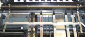
Static Eliminator Bar Mounted on Entry Side of Baumfolder 2020 Folder
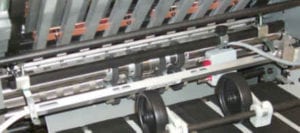
Static Eliminator Bar Mounted on Exit End of Baumfolder 2020 Folder
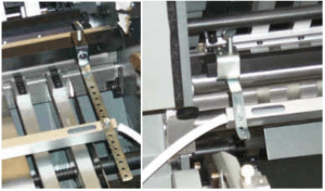
Entry Side Bracket (left) / Exit Side Mounting Bracket (right)
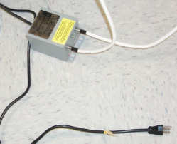
Power Pack with Bars connected
FK2001355/50 ADDITIONAL SLITTER SHAFT ASSEMBLY
This is an additional Slitter Shaft Cartridge set for the Baum 20PFF and CFF. The purpose of having an additional set of slitter shafts is to allow you to leave the tooling to remain in place for faster set up from one job to another.
For example if you do a lot of tri-folded newsletters you can have a set of shafts with the two scores and pull out tires in place for running newsletters. All you have to do is remove the slitter shaft cartridge you are using and replace it with the one with the two scores and you are ready to finish setting up your job. This saves you the time of adding or replacing tooling on jobs you run on a regular basis. Some customers have a number of these assemblies set up for a particular job and just select the proper set to use on that job.
This Slitter Shaft Cartridge comes with no additional tooling or pull out tires. You will probably need to purchase additional Score, Slit, or Perf Kits along with additional pull out tire assemblies depending on what the job is that you will be setting up on the extra set of slitter shafts.
FK2000170/50 SLEEVE-SHEET PULL OUT ASSEMBLY
This is a one Pull Out Tire Assembly for the slitter shafts for the Baum 20PFF and 20CFF Folder. This consists of 1 Pull Out Tire, 1 Sleeve-Sheet Pullout, 1 set screw. You will need to purchase additional of these assemblies when you purchase FK2001355/50 Slitter Shaft assemblies. The number required will depend on what the job is and what tooling is put on the slitter shaft assembly. A total of (8) of these Assemblies come standard with the parallel section of the Baum 20.
267-657-BG-01 SLITTING KIT (NO BLEED) 1-1/8” SLITTER SHAFT
This kit provides the tooling to do one line of slitting (with no center bleed) on a Baum 20 PFF or CFF and other Baum Equipment with 1-1/8” diameter Slitter Shafts. This allows you to cut folded sheets or flat sheets apart. More than one cut can be made by adding additional kits.
This kit contains (1) P/N 51943 Split Slitter Blade
267-658-BG-01 PERFORATING KIT 1-1/8 “ SLITTER SHAFT
This kit provides the tooling to do one line of perforation on a Baum 20 PFF or CFF and other Baum Equipment with 1-1/8” diameter Slitter Shafts. With this kit you can either perforate the heads of booklets (to allow the air to escape in making right angle folds) or to slot perforate sheets delivered flat. More than one perforation can be made by adding additional kits.
This kit contains (1) P/N 51940 15T, Split Perforator Blade and (1) P/N 51941 30T Split Perforator Blade.
267-658-BG-01 SCORING KIT 1-1/8” SLITTER SHAFT
This kit provides the tooling to do one line of the standard male-female scoring that comes standard with the Baum 20PFF and 20CFF 1600 Series Folders. This kit can be used to score a sheet and deliver it flat or score a sheet after a fold or folds have been made. More than one line of scoring can be done by adding additional kits
This kit contains (1) P/N 51947 Split Scoring Blade.
267-662-BG-01 CENTER TRIM KIT 1/8” 1-1/8” SLITTER SHAFT
This kit provides the tooling to allow you to slit and remove a 1/8” center trim (bleed).
This kit has (4) P/N 93209 Slitting blades.
267-663-BG-01 CENTER TRIM KIT 1/4” 1-1/8” SLITTER SHAFT
This kit provides the tooling to allow you to slit and remove a 1/4” center trim (bleed).
This kit has (4) P/N 93209 Slitting blades
263-780-BG-01 CENTER TRIM KIT 1/4” 7/8” SLITTER SHAFT
This kit provides the tooling to allow you to slit and remove a 1/4” center trim (bleed). This kit can only be used on older model folders with the 7/8” slitter shafts.
This kit has (2) P/N 06378 Slitting Blades and (2) P/NJ 06804 slitter blades.
267-660-BG-01 EDGE TRIM KIT L.H. 1-1/8” SLITTER SHAFT
This kit provides the tooling to allow you to trim the Left Hand edge from booklets or the outer edge of circulars running two or more up.
This kit contains (1) P/N 51943 Split Slitter Blade.
267-661-BG-01 EDGE TRIM KIT R.H. 1-1/8” SLITTER SHAFT
This kit provides the tooling to allow you to trim the Right Hand edge from booklets or the outer edge of circulars running two or more up.
This kit has (1) P/N 51943 Split Slitter Blade.
FK20022574 PERF-SLIT-PERF KIT 1-1/8” SLITTER SHAFT
This kit is for a special application when slitting and perforating two up work when gluing two up self-mailers when you need to slit apart the two pieces and do a perforation very close to the cut edge of both pieces to allow you to tear off the sealed edge when opening up the sealed self-mailer.
FK2002764 ACCU-SLIT SLITTER KIT 1-1/8” SLITTER SHAFT
The Accu-Slit kit provides better sheet control when slitting multiple up work. It contains special tooling that contain rubber tires for better control and drive of the sheets as they are being slit.
FK2002507 TRI-CREASER™ EZ- FIT CREASING TOOLING (1-1/8’ Slitter Shaft)
The Tri-Creaser™ EZ-Fit allows you to do letter press quality creasing of heavy weight digital printed material to reduce cracking when folded on the Baum 20 PFF and CFF Paper Folder. The EZ Fit requires you to remove the tooling to change the color coded ribs in the male scoring assembly.
FK2002504 TRI-CREASER™ FAST FIT CREASING TOOLING (1-1/8’ Slitter Shaft)
The Tri-Creaser™ Fast Fit allows you to do letter press quality creasing of heavy weight digital printed material to reduce cracking when folded on the Baum 20 PFF and CFF Paper Folder. The Fast Fit version utilizes split creasing ribs which means you do not need to tooling to change the color coded ribs in the male scoring assembly. This results in fast job set up.
FK2003428/1125 TRUESCORE PRO HEAD (1-1/8’ Slitter Shaft)
The Rosback TrueScore-Pro Scoring System is designed for scoring sensitive materials such as digitally printed stock to reduce cracking. Digitally printed materials show a persistent tendency to crack when folded, spoiling many high quality cards, mailers, and covers. Excellent results are also obtained on coated paper, as well as UV, aqueous, and varnish coated stock
FK2000418 MICRO-PERF KIT (1-1/8’ Slitter Shaft)
This kit allows you to do an extremely fine line of perforation (72 per inch) on the Baum 20. This is ideal for tear-offs such as self-mailers with a coupon or reply card. The microperf produces a crushed rather than a cut perforation, so the sheets lay flat to feed better through a copier or laser printer.
ADDITIONAL/SPARE PERF/SLIT/SCORE BLADES
51940 Blade-Perf 15T Split (1-1/8” Slitter Shaft)
51941 Blade-Perf 30T Split (1-1/8” Slitter Shaft)
51942 Blade-Perf 50T Split (1-1/8” Slitter Shaft)
53425 Blade-Perf 86T Solid (1-1/8” Slitter Shaft)
FK 0000124 Blade-Perf 86T Split (1-1/8” Slitter Shaft)
FK0000386 Micro Perf Blade-72T (1-1/8” Slitter Shaft)
51943 Blade-Slitter Split (1-1/8” Slitter Shaft)
51947 Blade- Score Split (1-1/8” Slitter Shaft)
714 Table-Top Folders
1. Turn the pump on and set air to maximum.
2. Set vacuum at “5″.
If you cannot obtain the proper vacuum or air, check the following: A) Clean the pump filters. B) Check hose connections from the pump to the folder, or check for blockage in hoses. C) Contact your local dealer for service.
3. The caliper assembly should be positioned 90 degrees relative to the feed table.
4. There are two holes in the air tube (front blow) on the caliper assembly. These holes should be pointed towards the scribe line on the feeder table below the caliper. When the air is turned on, the bottom sheet should be blown down to the sucker wheel. If not, adjust the blow tube.
5. If the paper is stumbling on the cut out for the sucker wheel or not feeding properly, disconnect the air hose from the folder.
–Line the front edge of the holes in the sucker wheel with the orange tab (the side you put the paper against). See Figure A.
–Lay a sheet of 20 lb. bond paper on the feed table to cover the first set of sucker wheel holes with the leading edge of the paper. Turn on the pump. (Not the folder)
–Turn the handwheel until the leading edge of the paper is past the orange tab. The vacuum should release when the leading edge of the paper is 1/8″ past the orange tab.
–If the paper does not release at 1/8″, A) Remove the feed table. Then B) Loosen the set screw in the sucker wheel feed block closest to the fold rolls 1/4 turn. Tighten the set screw farthest from the fold rolls 1/4 turn. NOTE: Make sure the feed block has a little rotational movement (1/32″). If not, loosen the screw. Now C) Repeat 1/4 turn adjustments until the 1/8″ setting is obtained.
6. If the sucker wheel doesn’t pick up the sheet, reverse the procedure of adjusting the set screws as explained in #5 above.
7. Make sure 1/8″ flat washer is NOT between the sucker wheel and the feed block.
8. Make sure the sucker feed block hole is not plugged.
If these items do not resolve the problem please contact your local dealer, or contact our Technical Support group at 1-800-543-6107.
The Drive motor shutting off is the result of a mechanical bind or an electrical problem.
The first thing to check is to make certain the folder is setting level and that the fold pans are not rubbing the fold rolls.
If the above items are okay I would remove the non-operator side guard. Then remove the belt from the motor. Run the motor to see if it still shuts off. If the motor does shut off then you know it is a problem with the motor or switch and you need to call 1-800-543-6107 and ask for technical support.
If the motor does not shut off then you have a mechanical bind. In the older 714’s (serial numbers beginning with 82 thru 90) the bearings on the ends of the fold rollers need to be lubricated periodically with a lightweight oil. Also the gears that drive the feed table and the stacker also need to be lubricated with lightweight oil. These gears are located on the inside of the non-operator side frames between the feed table and the stacker.
Another item that could be causing the problem would be the slitter shaft thumb screw that tightens into the frame. This screw should only be into the frame a couple of threads. If it is tight it could cause a bind.
If these items do not resolve the problem please contact our Technical Support group at 1-800-543-6107.
PERFORATING
The Ultrafold can be used to perforate either the folded sheet (to assist in making a right-angle fold) or to perforate sheets delivered flat. Baumfolder supplies one standard 41-tooth perforator blade. Additional perforator blades are available throught the Baumfolder Parts Department at 1-800-543-6107.
The perforator blade should be mounted loosely to the blade holder with the retainer collar to give better support to the perforator blade. Always be sure that the flat side of the blade is against the blade holder. Loosen the brass-topped set screws in the perforator collar and blade holder before attempting to place them on the slitter shafts.
The perforating blade holder assembly is then slid onto the upper slitter shaft along with the necessary pull-out tire assemblies. Then tighten the screws holding the perforator blade to the blade holder, aligning the blade to the holder. This allows for free horizontal movement on the shaft.
Side the grooved perforator collar onto the lower slitter shaft along with the other pull-out tire assemblies. The flat side of the perforator blade should just touch the side of the groove in the perforator collar. See Figure 17.
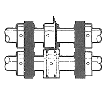
Figure 17
The perforator collar and blade holder can be lid to the desired position on the slitter shaft, then lock the blade holder and perforator collar into position with the brass-tipped set screw.
The perforator stripper fits onto the slitter shaft bar in between or next to the perforating blade. (see Figure 18) This strips the paper off for delivery and prevents it from wrapping around the perforator blade.

Figure 18
SCORING
The Ultrafold can be used to score a sheet and deliver it flat, or to score a sheet after a fold or folds have been made.
To ensure accuracy in making right-angle folds, always score the sheet where the fold is to be made. This applies in all instances when a perforator cannot be used.
Attach the scoring blade loosely to the blade holder for mounting on the slitter shaft. Scoring blades can be mounted on either the upper or lower slitter shaft. Once on the shaft, tighten the screws, aligning both the blade and the collar. This allows free horizontal movement on the shaft. Scoring blades should be placed so that the fold will be made with rather than against the scoring, or, in a continuing direction to the pressure of the crease that has been applied by the scoring blade.
For a wide, well-rounded score, use the two steel scoring collars. (See Figure 19) Sharpness and the depth of the score can be controlled by regulating the distance the collars are placed away from the scoring blade.
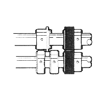
Figure 19
The scoring collars can also be placed on either side of the rubber scoring collar. The two collars can be compressed against the rubber collar, causing the rubber to bulge up for a deeper score. (See Figure 20).
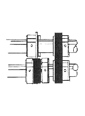
Figure 20
Due to the increase use of copy machines and laser copiers, it is becoming more and more difficult to do the Z fold and the Engineering fold on these folders.
If you are doing, or are planning to do, a large quantity of these folds you may want to slow down the feeder.
(Contact your dealer for service)
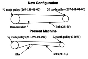
This can be accomplished by changing 2 pulleys and one belt that are located under the non-operator’s side guard.
The part numbers you need to order are:
- 267-139-01-00 72 tooth pulley
- 267-141-01-00 20 tooth pulley
- 24165 belt
- Square the guide with the fold rollers.
- Remove the number 1 fold plate (top fold plate).
- Take an 11 x 17 sheet of paper that is cut square and lay on feed table against one of the side guides.
- Hand feed the sheet into the folder and watch the sheet come out of the first set of rolls. Watch the sheet to see if it comes out square, or if one corner comes out before the other. If one corner comes out before the other you know you are not feeding square.
- Referencing the diagram above, loosen the rear locking screws on the back of the side guide, then push in the micro-adj. knob and rotate the back of the side guide in the direction that the back of the paper needs to move to square the side guide. Once you have moved the side guide retighten the rear locking screws.
- Repeat step 3 to see if the paper is now coming out square. If not repeat step 4 until side guide is square.
- When you get the side guide square then loosen the collar and rotate it until the micro-adj. knob falls back on to it then retighten the collar.
- Then align the other side guide to the first side guide using the square sheet of paper.
There are two things to check, both dealing with the top sensor (the sensor located right above where the paper feeds into the fold rolls):
- The bottom of the sensor must be even with the bottom of the nip guard, which it is mounted to. If it is not even, loosen the screw in the sensor and reposition it.
- Is the sensor lined up with the hole in the feed table? If it is not lined up, loosen the screw holding the sensor and adjust the sensor, remembering step 1 above.